Evaluating Logic Circuits with Ternary Logic Graphs
This article describes how a basic RS NOR flip-flop circuit can be simulated using a directed graph constructed with source nodes (which output a value to nodes), terminal nodes (which take input from nodes), and gate nodes (which take input from nodes, do something with it, and provide the output to nodes). This graph propagates changed values to simulate the flow of electricity in the real-life logic circuit. It is based on a ternary logic system, which consists of a third unknown value in addition to the normal true and false values. In this article, balanced ternary is used to represent these values: +1 for true, 0 for unknown, and -1 for false. The language used in this article is Swift, as I wanted to try it out here by building (the bones of) a circuit simulator iOS app.
The Logic Graph
Logic nodes are based upon two main protocols, which set out what nodes that provide output to the graph and a nodes that take input from the graph should do. Ternary values are represented by the type TValue, a typealias of Int.
The following structure represents an input to a logic node. This defines the node that the input is connected to, and the index of the input (this is useful when the referenced logic node has more than one input connection):
struct LogicNodeInput {
    var node: LogicNode
    var index: Int
}
The protocol for a node that provides an output to the graph (such as a button) is defined below:
protocol OutputNode {
    var outputValue: TValue { get set }
    var childInputs: [LogicNodeInput] { get set }
}
Each node providing an output to the graph has an array of child inputs, which are inputs that the source node is connected to in the logic circuit. When the node providing an output changes its outputValue, it passes the updated value and the corresponding input index to each node in its childInputs array using the update function, as shown by this implementation:
var outputValue: TValue {
    didSet {
        for input in childInputs {
            input.node.update(input.index, newValue: outputValue)
        }
    }
}
The other main protocol is for a node that takes an input from the graph, such as a lamp. This complements the OutputNode protocol to form a prototype for the I/O of a gate node.
protocol InputNode {
    var inputValues: [TValue] { get set }
    func update(inputIndex: Int, newValue: TValue)
}
As you can see, nodes that takes an input from the graph implement an update function, which is called by the OutputNode implementer whenever an input to the node changes. An example of a class which implements of this function is the TwoGateNode class, the base class for all logic gates with two inputs:
class TwoGateNode : LogicNode {
    var gateName : String
    var logicGateFunc: ((TValue, TValue) -> TValue)?

    init(gateName: String, children: [LogicNodeInput] = []) {
        self.gateName = gateName
        super.init()
        self.childInputs = children
        self.inputValues = [tunknown, tunknown]
    }

    func eval() -> TValue {
        return logicGateFunc!(inputValues[0], inputValues[1])
    }

    // Override definition of update() in LogicNode class
    override func update(inputIndex: Int, newValue: TValue) {
        inputValues[inputIndex] = newValue
        delegate?.newInputValue(inputIndex, newInputValue: newValue)

        let newOutput: TValue = eval()

        if (newOutput != outputValue) {
            outputValue = newOutput
            delegate?.newOutputValue(newOutput)

            for input in childInputs {
                input.node.update(input.index, newValue: newOutput)
            }
        }
    }
}
Simulating an RS Latch
The RS NOR flip-flop circuit contains two source nodes, two gate nodes, and two terminal nodes. Initially their values are initialized to 0 (unknown):
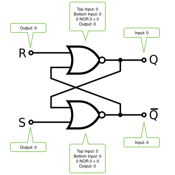
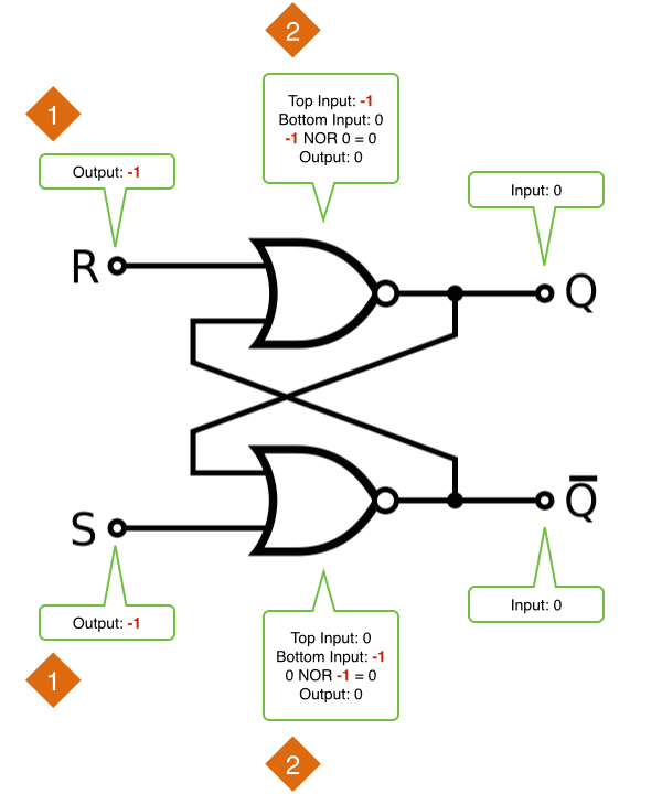
If we set R and S to false, so that the latch is neither being set nor reset, the output (Q) remains unknown, as the state held by the latch is unknown:
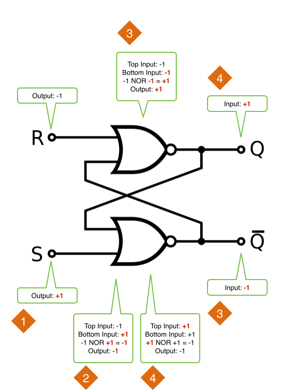
Setting R to true resets the flip-flop, setting the value of the latch to false:
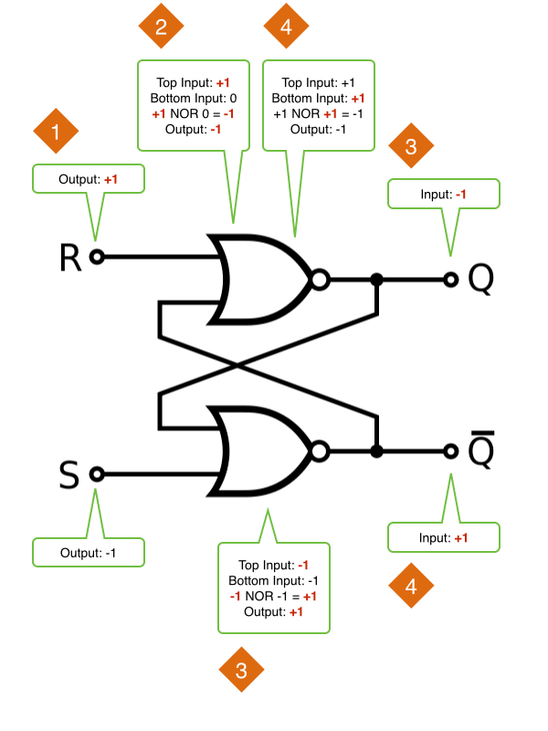
In step 1, the value of the reset node is updated. The reset node then updates its child, the NOR node. The updated input causes the NOR node to evaluate to false, as 1 NOR 0 = -1. As its value has changed, the NOR node now updates its children: the Q node and the second NOR node. This second NOR node now evaluates to true, as -1 NOR -1 = +1. Therefore, it updates its children: the Q̄ node and the first NOR node. The first NOR node reevaluates itself with the new input, but its output remains the same, so it does not need to update its children and the update process is concluded.
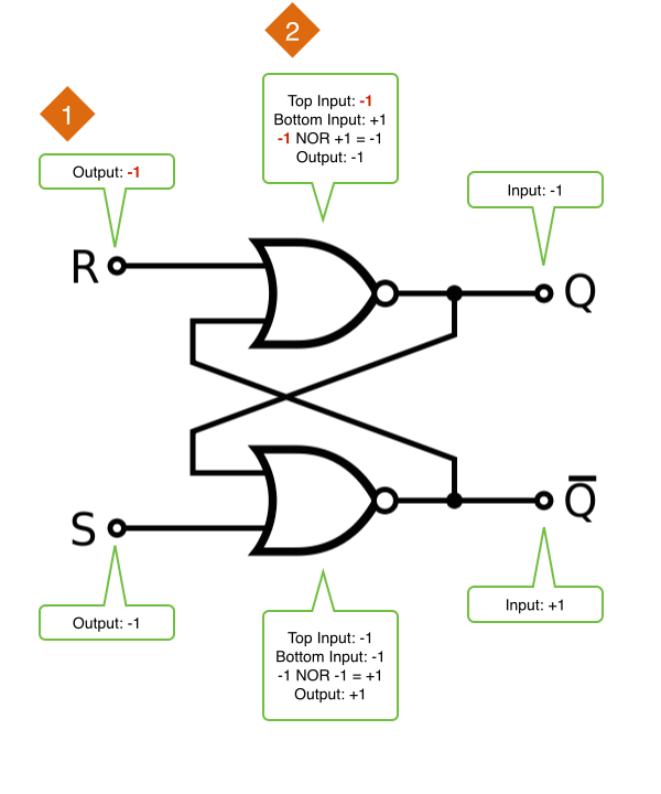
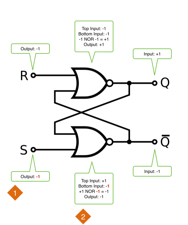
Setting R to false causes this new value to be propagated to the top NOR node, but the value of the NOR node does not change as the latch retains its state:
Setting S to true sets the value of the latch to true. Because the design of the flip-flop is symmetrical, setting S to true causes the same events to occur except with the vertically opposite nodes. Instead of Q being set to true and Q̄ to false, Q̄ is set to true and Q to false:
Finally, as with setting R to false, setting S to false causes propagation of S=-1, but again the value of the NOR node does not change, and the latch retains its state:
Here is a demonstration of an RS latch created with this circuit simulator running in the iOS Simulator. Notice how both lamps remain off until the reset button is toggled, indicating that the value of Q was initially unknown: